Control and monitoring
The sequence of events logging and the recording of the waveform capture (16 samples/power cycle), provide the user with all of the useful information on the electrical network status. This features allow continual and full monitoring in normal operation as well as in the event of a system fault. High accuracy measurements may replace measuring instruments and transducers.
Direct measurements
For every input channel, the amplitude (RMS), phase and period for the fundamental and harmonic components are provided.
- Frequency,
- Phase & residual currents and voltages,
- Phase & residual currents and voltages,
- Harmonic components,
- Directional currents, etc
Computed measurements
On the basis of the direct measurements, the following are processed: phase-to-phase voltages, residual voltage and current, sequence components, powers, impedances, energy, demand values (equivalent thermal current, fixed, rolling, peak and minimum demand of phase currents, powers, etc...).
Besides the input values, a lot of relevant information are available; i.e: tripping counters, number of CB close commands, duration of the CB open and close operations, number of automatic reclosing commands, date and time, relay ID data, identification code, serial number, firmware version, rated parameters, etc.
Sequence of events logging
Several useful data are stored for diagnostic purposes; the events are stored into a non volatile memory:
- Sequence of Event Recorder (SER)
A The event recorder runs continuously capturing in circular mode the last three hundred events upon trigger of binary input/output or any setting change. Event cause, counter and time stamp are recorded for every event.
- Sequence of Fault Recorder (SFR).
The fault recorder runs continuously capturing in circular mode the last twenty faults upon trigger of binary input/output and/or element pickup (start-trip). Fault cause, counter, time stamp and meaningful measures are recorded for every fault.
- Partial & total counters
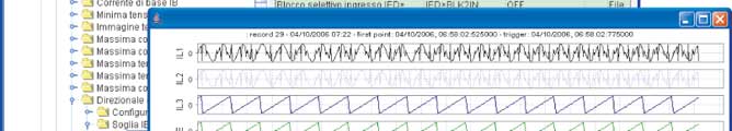
Digital Fault Recorder (DFR)
Upon an adjustable trigger (start/trip, binary input and/or Thysetter command), the relay records in COMTRADE format:
- Oscillography with instantaneous values for transient analysis
- RMS values for long time periods analysis
- Logic states (binary inputs and output relays).
Products